Showing posts with label A2. Show all posts

Wednesday, May 2, 2012

A2 - Hudson

My bridge looks strange because I didn't want to go with a typical truss design, but I also didn't want my bridge to be really expensive. I wanted to try and make my bridge different, but still make it effective, so instead of right triangles along the sides, I made diamonds. It was an interesting test, but it made me realize why most bridges follow set designs - they're simply stronger for less money. In addition to that, I learned that bridges that seem stable can collapse in certain areas that seem strong, which is something an engineer would need to look out for, because, while in theory the bridge might look good, it really isn't.

Plan View

Elevation View
Bridge Cost Spreadsheet


Tuesday, May 1, 2012

A2 - Lester


The truss was made with interconnecting right triangles in a rectangular shape that comes to points at either end. Triangles are the strongest structures and can bear the most weight in a stress test, as opposed to rectangles which could morph and bend. Pieces include blue (2.215”) and yellow (3.375”) K’nex chords, as well as 180 degree gusset plates and 360 degree gusset plates to serve as connectors. The top has only 180 degree gusset pieces to keep a flat surface for the testing board to be placed. The two sides of the bridge are connected by yellow (3.375”) pieces that are securely fastened in the unused snaps of the 180 degree gusset plates. The images show the basic structure of the design, but do not show the connecting gusset plates due to their complex shapes. The length of the bridge is estimated at this point since the connecting gussets are not taken into account. They are not essential to illustrating this first-draft model, although they are essential in cost calculations. Future models will show the connecting gusset plates and incorporate the exact dimensions of the K’nex chords and gussets.
My bridge did not change much during the design. I began with the intentions of using right triangles, since K’nex pieces are made with the intention that each piece completes a right triangle with the next largest size. This knowledge helped me choose the pieces I wanted to use; the blue and yellow chords fit perfectly with my design intentions. The only aspect that changed was the type of connecting gussets being used. At first, I used the 360 degree gussets for all connections. Later in the design process I realized that a flat top bed would be needed, so I switched to the 180 degree gusset connectors.
During this process, I realized that K’nex pieces are made with precise dimension that perfectly connect with each other in successive right triangles. I worked with the Autocad – Architectural Desktop program for the first time in a few months and was able to refresh my memory of the features it has available. I practiced creating a design that was both functional and cost efficient, something that will be essential in future academic and real-world problems. 

-Belinda Lester

A2-DURKIN


            The goal for the design of this bridge was to create a bridge with the lowest ratio of the cost of the bridge to the weight of sand in kilograms that the bridge can hold. This means that design of the bridge must be incredibly efficient, only using pieces that are important to stability. This is why I chose to build an above ground bridge with a single layer of members. When originally designing a bridge in WPBD an underneath bridge was most effective however this is not true when working with K’NEX.  With K’NEX it is better to use an above ground design because it is easier to design the bridge in a way that it will be stable when rested on the table. The connections between either side of the bridge were decided on based on the constraints of a flat 8” wide portion at the top of the bridge as well the necessity that the bridge stay together in the middle when pressed under the weight of the sand. This was harder to decide on as it was not possible to decide on the connections on WPBD where the program just made the connections for you. The length of the bridge was based of the constraint of being at least 2’ long combined with cost efficiency which caused the decision to not make it much longer than 2’. 

Figure 1: Elevation of Bridge Design (side view)


Figure 2: Plan of Bridge Design (top view)

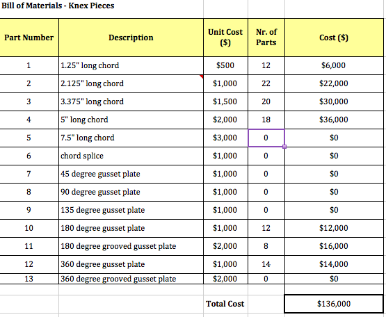
Figure 3: Truss Bill of Materials; the spreadsheet calculating the cost of the bridge.


Originally the bridge was designed with the sole goal of stability, this was then found to be way too expensive.  After this initial design a second design with the lowest possible cost was drawn up but after thinking through the execution of the design it was realized that it would be entirely too unstable.  Once the goal of a low cost to failure load ratio was considered more thoroughly many different designs that seemed to be a good compromise were drawn up.  Once the constraints came into consideration that above ground bridge seemed to be the most stable design and since the top of the bridge needed to have a flat top central region it was decided that keeping the entire top flat might be the most effective as it would help distribute the weight.
Designing this bridge taught me a lot about the difference between what works on the computer and what will actually work in the real world.  I also learned the importance of understanding all parameters and factors before creating a design as a design may be very strong or very pretty or very cheap but if it does not meet the constraints it useless.