This term I learned a lot about bridges that I never knew before. I learned about different types of bridges - truss, suspension, etc. - and how these bridges work and I learned a lot about bridge failure along the way.
Through the use of the West Point Bridge Design software I learned about tension and compression and how bridges work in general. I learned how bridges were likely to collapse and what bridge designs wouldn't work at all due to they way they were constructed.
Through the use of Knex I learned that sometimes the way you model bridges isn't actually how the bridges will turn turn out and the way you predict failure isn't always how the bridge will actually fail. I learned that some bridges can look simple and be deceptively strong, and others can look strong but break under the slightest pressure.
The most important part of bridge designing, though, was doing the actual analysis and using Physics and Trig to figure out how the bridge would break, how much weight would be distributed where, etc. Even though WPBD gave all of these numbers, without context it really made no sense. I could tell you where the bridge was going wrong, but I couldn't tell you why. Doing the actual analysis helped me see how it all works together to make the cohesive product.
This week I hope to have our bridge do well in testing - hopefully over 30 pounds or the modifications would not have been worth it. Our bridge nearly doubled in cost but I don't know if the ratios will be any better considering we had an inexpensive bridge before that held 18 pounds where as much more expensive bridges could only hold up to about 40.
Next week I look forward to doing my final assessments on what I did and learned throughout the term.
Showing posts with label Stephanie Hudson. Show all posts
Showing posts with label Stephanie Hudson. Show all posts
Wednesday, May 30, 2012

Wednesday, May 23, 2012
Hudson - Week 8
Q) Is [the Method of Joints] analysis sufficient for a real bridge? If not, why not?
I think that the Method of Joints analysis is close but not completely sufficient for a real bridge. Due to human calculating errors, I think that the MoJ analysis could prove faulty because it is a lot of calculations with quite a few places where a calculation could go wrong and throw off every calculation after that. For that reason, I would say that a computer program in addition to the MoJ analysis would be the safest way to figure out the various tension and compression forces on each member of the bridge.
Q) What further would you like to analyze and what knowledge or tools might assist you?
I think that the tension/compression force analysis is sufficient when coupled with cost to weight ratios. Using the MoJ analysis gives me a lot of information I can use in conjunction with the various bridge software to design the best possible bridge under the specifications of this project.
This week my group plans to modify our bridge again basing the new design off of a revised version of our old design that is not only within the final specifications of the project, but that also uses the MoJ analysis and the Bridge Designer software to strengthen the main frame of the bridge.
Next week my group plans to continue revising and testing the bridge using the MoJ analysis to compare tension and compression forces between various bridge designs.
I think that the Method of Joints analysis is close but not completely sufficient for a real bridge. Due to human calculating errors, I think that the MoJ analysis could prove faulty because it is a lot of calculations with quite a few places where a calculation could go wrong and throw off every calculation after that. For that reason, I would say that a computer program in addition to the MoJ analysis would be the safest way to figure out the various tension and compression forces on each member of the bridge.
Q) What further would you like to analyze and what knowledge or tools might assist you?
I think that the tension/compression force analysis is sufficient when coupled with cost to weight ratios. Using the MoJ analysis gives me a lot of information I can use in conjunction with the various bridge software to design the best possible bridge under the specifications of this project.
This week my group plans to modify our bridge again basing the new design off of a revised version of our old design that is not only within the final specifications of the project, but that also uses the MoJ analysis and the Bridge Designer software to strengthen the main frame of the bridge.
Next week my group plans to continue revising and testing the bridge using the MoJ analysis to compare tension and compression forces between various bridge designs.
Hudson - A3
 |
| Image 1: First page of Method of Joints calculations |
 |
| Image 2: Second page of Method of Joints calculations |
 |
| Image 3: Truss Diagram with Forces |
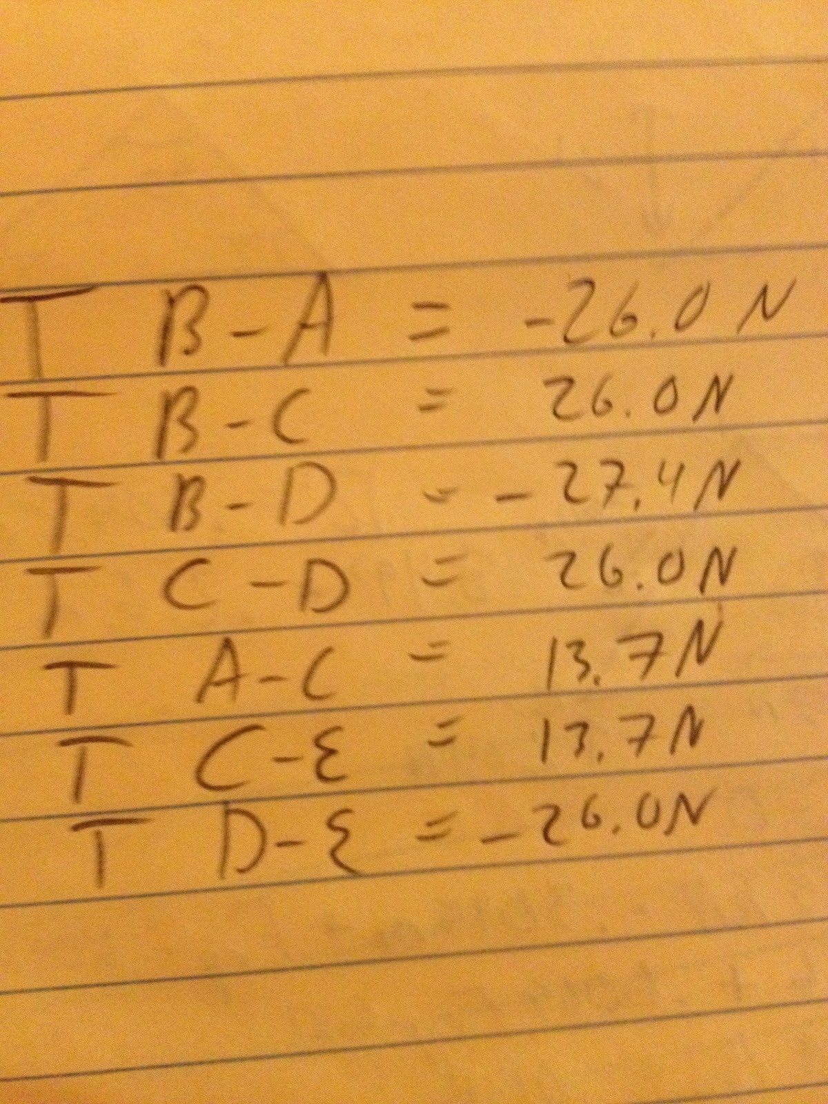 |
| Image 4: Table of Tensions with Member to Member Labels |
 |
| Image 5: Bridge Designer of Fictitious Truss |
 |
| Image 6: Bridge Designer of Knex Truss |
5.2) The largest force in the Knex truss when you scale off of the Bridge Designer numbers would be approximately 60 which would be found in the middle of the bridge when using 20 pounds of weight. This falls into the expected range of 0-100 before the bridge would break. The forces get larger the closer they get towards the middle of the bridge on the outer edges, but the inner cross-sections have the same tension through-out. While this is possible, it's not entirely plausible which could be the result of the way Knex hold weight.
6) This type of analysis is useful because it allows us to quickly see how what the compression and tension forces are in our bridge so we can modify our bridge accordingly. When you couple this with the information about how knex hold up under different forces you can predict how the knex are going to behave under certain weights and modify the bridge structure to work around these failings.
Wednesday, May 16, 2012
Analysis Desires - Hudson
When testing the bridge last week, we had an inexpensive bridge that only held 18 pounds of sand compared to 45+ pounds of other bridges that were more expensive. When we redid our bridge to make it stronger it only held about 10 more pounds and cost about twice as much, so we reverted back to our old bridge. This process - test, rebuild, test, unbuild - took the entire 2 hour class period. Clearly, this is a rather inefficient method of designing a bridge.
When using WPBD it was easy to see the ratios and the cost in an instant when you changed your bridge and you could change your bridge time after time, start new bridges, continue old bridges, and just all around get more data in two hours than by hand with the knex. For this reason, I think it would be nice to have a simple way of calculating cost-load ratios and it would help to know approximately how much stress certain types of triangles can take before something snaps. This would help tremendously when designing the bridge because if certain triangles at certain angles hold more weight effectively, it would be easier to design a bridge using those triangles and then test it and tweak it than just blindly assembling knex pieces and hoping for the best.
This week I hope my group can figure out basic ways to analyze our bridge design and possibly attach some numbers to it so that between this week and next week we can rebuild and/or tweak our bridge design so that it is more effective overall.
When using WPBD it was easy to see the ratios and the cost in an instant when you changed your bridge and you could change your bridge time after time, start new bridges, continue old bridges, and just all around get more data in two hours than by hand with the knex. For this reason, I think it would be nice to have a simple way of calculating cost-load ratios and it would help to know approximately how much stress certain types of triangles can take before something snaps. This would help tremendously when designing the bridge because if certain triangles at certain angles hold more weight effectively, it would be easier to design a bridge using those triangles and then test it and tweak it than just blindly assembling knex pieces and hoping for the best.
This week I hope my group can figure out basic ways to analyze our bridge design and possibly attach some numbers to it so that between this week and next week we can rebuild and/or tweak our bridge design so that it is more effective overall.
Wednesday, May 9, 2012
Knex review - Hudson
Looking back over my post from last week I agree with everything I wrote. Working with knex more made me realize how much more they need a larger variety of pieces at different angles. Some things are just not possible with knex and that makes no sense when you're trying to make a scale model of a bridge you want to build.
The knex also break in strange ways that the bridges can't actually break. Pieces of bridges won't just slip out of the joints, which is one major project with knex. A real bridge might not break in those places. Bridges made out of knex also flex together and apart which real bridges wouldn't do. Overall it's still a really good medium to work with your hands when you're modeling your bridge, like I said in my last post.
I think the difference between knex and designing a real bridge would be the ways the bridges break and how they can be constructed, along with the materials, like I said last week. The materials only come one way with knex, which makes it difficult to judge how weak you can get a certain beam before it breaks. Steal is also a lot less flexible than the plastic knex so they aren't entirely accurate when it comes to how the bridge behaves under stress, much like the WPBD software overexaggeration of how the bridge would bend.
Building a real bridge out of steel would be a lot more realistic, even if you were just making a scale model. You could weld the pieces together and do tests on them that would work better since you're making it out of the same materials that you're making the bridge out of, though you can't just snap the pieces apart if you do that. You have to be fairly certain of your design before you start to construct it, so it requires a lot more initial planning.
For this week I hope to see the ways in which our bridge breaks and improve on it from there. We can also get a base model for the strength vs cost ratio that our final design might follow.
For next week I want to improve on our bridge and make it stronger, while also understanding how knex interact with each other so we can try to fix how they go together. That might stop the beams from sliding out of the grooves or we could make the design better so that it isn't even a possibility that the beams slip out.
The knex also break in strange ways that the bridges can't actually break. Pieces of bridges won't just slip out of the joints, which is one major project with knex. A real bridge might not break in those places. Bridges made out of knex also flex together and apart which real bridges wouldn't do. Overall it's still a really good medium to work with your hands when you're modeling your bridge, like I said in my last post.
I think the difference between knex and designing a real bridge would be the ways the bridges break and how they can be constructed, along with the materials, like I said last week. The materials only come one way with knex, which makes it difficult to judge how weak you can get a certain beam before it breaks. Steal is also a lot less flexible than the plastic knex so they aren't entirely accurate when it comes to how the bridge behaves under stress, much like the WPBD software overexaggeration of how the bridge would bend.
Building a real bridge out of steel would be a lot more realistic, even if you were just making a scale model. You could weld the pieces together and do tests on them that would work better since you're making it out of the same materials that you're making the bridge out of, though you can't just snap the pieces apart if you do that. You have to be fairly certain of your design before you start to construct it, so it requires a lot more initial planning.
For this week I hope to see the ways in which our bridge breaks and improve on it from there. We can also get a base model for the strength vs cost ratio that our final design might follow.
For next week I want to improve on our bridge and make it stronger, while also understanding how knex interact with each other so we can try to fix how they go together. That might stop the beams from sliding out of the grooves or we could make the design better so that it isn't even a possibility that the beams slip out.
Wednesday, May 2, 2012
WPBD vs Knex - Hudson
Both of these tools are extremely fun and useful to build bridges. WPBD is semi-hands on in its approach in that there aren't many set designs to choose from, but building with the Knex allows you to really understand the difference in bridge strength.
WPBD and Knex are similar in that, in a way, you can understand how strong the bridge is that you made with each of them. They both also allow easy corrections and fixes.
WPBD is superior to Knex in that it tells you where your bridge will break, if it's a feasible idea, and the relative ratios on each member. WPBD also allows angles and thinner/thicker members that Knex does not. Knex are superior in that they allow you to actually feel the bridge you're designing and you can see how the pieces are going to break when they do and try to design around that instead of just making that member larger and stronger, because it's usually not the member that breaks, it's the joint.
Overall, I think both the WPBD software and Knex are good ways to get a feel for your bridge and understand how it works.
WPBD and Knex are similar in that, in a way, you can understand how strong the bridge is that you made with each of them. They both also allow easy corrections and fixes.
WPBD is superior to Knex in that it tells you where your bridge will break, if it's a feasible idea, and the relative ratios on each member. WPBD also allows angles and thinner/thicker members that Knex does not. Knex are superior in that they allow you to actually feel the bridge you're designing and you can see how the pieces are going to break when they do and try to design around that instead of just making that member larger and stronger, because it's usually not the member that breaks, it's the joint.
Overall, I think both the WPBD software and Knex are good ways to get a feel for your bridge and understand how it works.
A2 - Hudson
My bridge looks strange because I didn't want to go with a typical truss design, but I also didn't want my bridge to be really expensive. I wanted to try and make my bridge different, but still make it effective, so instead of right triangles along the sides, I made diamonds. It was an interesting test, but it made me realize why most bridges follow set designs - they're simply stronger for less money. In addition to that, I learned that bridges that seem stable can collapse in certain areas that seem strong, which is something an engineer would need to look out for, because, while in theory the bridge might look good, it really isn't.
 |
| Plan View |
 |
| Elevation View |
 |
| Bridge Cost Spreadsheet |
Wednesday, April 25, 2012
Process Observations - Hudson
While working with the West Point Bridge Design software, there are a few things I have noticed.
1) The bridge design will only show one truck going across one way. This is a fairly unrealistic scenario for a two lane bridge. Chances are, at some point there are going to be multiple cars going multiple directions at different places on the bridge and it seems like this is one area where the WPBD software isn't exactly the best.
The software also doesn't take into account weather forces. Constant wind, rain, ice, sun, or a mixture of these forces can be the downfall of a bridge. Frequent freezing and thawing can create micro-cracks in the structure and wind could cause the structure to bend in unusual ways.
2) The bridge cost does not take a lot of other factors into consideration. While joints and bars are important, what is more important is the cost of labor, foundation, decking, paving, nuts and bolts... there are a lot more considerations when building a bridge than just the joints and bars.
The bridge cost also seems to be outdated. While theoretically I can build a bridge for $250,000, that's probably not the case if I was to actually set about building the bridge I designed.
3) The bridge can't be modeled over time. Bars and beams are going to get weaker over time and if the bridge is painted frequently that's added weight and stress on the bridge that isn't being taken into consideration. If the bridge just barely passes to begin with, over time the structure might become weak enough that it collapses.
With this in mind, I still think the WPBD software is excellent for beginning bridge designs and our uses. It's not overly complicated, but it still has several different options for most choices. It helps people get a basic understanding of what works and what doesn't work and a ballpark range of what the bridge might cost.
1) The bridge design will only show one truck going across one way. This is a fairly unrealistic scenario for a two lane bridge. Chances are, at some point there are going to be multiple cars going multiple directions at different places on the bridge and it seems like this is one area where the WPBD software isn't exactly the best.
The software also doesn't take into account weather forces. Constant wind, rain, ice, sun, or a mixture of these forces can be the downfall of a bridge. Frequent freezing and thawing can create micro-cracks in the structure and wind could cause the structure to bend in unusual ways.
2) The bridge cost does not take a lot of other factors into consideration. While joints and bars are important, what is more important is the cost of labor, foundation, decking, paving, nuts and bolts... there are a lot more considerations when building a bridge than just the joints and bars.
The bridge cost also seems to be outdated. While theoretically I can build a bridge for $250,000, that's probably not the case if I was to actually set about building the bridge I designed.
3) The bridge can't be modeled over time. Bars and beams are going to get weaker over time and if the bridge is painted frequently that's added weight and stress on the bridge that isn't being taken into consideration. If the bridge just barely passes to begin with, over time the structure might become weak enough that it collapses.
With this in mind, I still think the WPBD software is excellent for beginning bridge designs and our uses. It's not overly complicated, but it still has several different options for most choices. It helps people get a basic understanding of what works and what doesn't work and a ballpark range of what the bridge might cost.
Wednesday, April 18, 2012
Research Questions - Hudson
1) Are bridges stronger when they are built with trusses supporting the weight from below or above?
2) What famous truss bridges are still standing throughout the world?
3) What is the longest truss bridge that can be built that still supports traffic?
2) What famous truss bridges are still standing throughout the world?
3) What is the longest truss bridge that can be built that still supports traffic?
A1-Hudson
1) My bridge design goal was to make the most cost effective bridge possible. My bridge is the shape it is because I found this shape to be the most cost effective and it seemed to bear the weight of the bridge better than my first designs.
2)
3)
2)
 |
| Image 1: 2D view of the bridge in Drawing Board mode. |
 | ||||||
| Image 2: View of the bridge in Test mode with a truck in the center.
4)
5)
During the designing process, I went from attempting to build a bridge where the weight of the bridge is supported by trusses that are over the bridge (Image 5) to a bridge where the weight was supported by trusses under the bridge (Image 1 and Image 2). I found this to be more cost effective and less prone to errors. I started out this way because most of the bridges I have ever seen have the weight supported from above rather than below, but while designing my own bridge I realized there were far too many problems with how the weight is distributed while the truck is crossing the bridge.
6) My current bridge cost, as seen in Image 1, is 393,202 dollars and 44 cents. I think this could be brought down to under 350,000 dollars at least, possibly even under 300,000 dollars with further time and knowledge by eliminating bars and joints.
7) While building this bridge I learned that sometimes designs that seem good on paper do not actually work out in real life. My bridge would seem stable but when the truck drove onto the bridge it would buckle in unexpected places, like the very middle of the road. I also learned that there are some support bars that are fundamental to whether the bridge will work or not and other bars that, while they seem important, can be taken out with no major impact to the strength and durability of the bridge.
|


Tuesday, April 10, 2012
Teamwork
Teamwork is an important part of Engineering. There are so many components to any Engineering project that it's just unrealistic for any one person to be able to bear the entire workload, and, thus, Engineering generally involves teams. In my past two Engineering classes I have had the misfortune of being put into teams with males who clearly believe that women have no place in Engineering. For that reason, I'm glad I'm with two other girls who seem to want to work in a team just as much as I do. While, quite often, "teamwork" translates into one person doing the work and three people getting credit, I don't think that will be the case in this class.
In order to keep everyone doing their fair share and to get all the work done in time we are going to need to budget our time effectively and communicate well. I don't see this as a setback in our group because we are communicating effectively already. We will need to keep this up though, to make sure that our ideas mesh well together and we can work out any conflict that arises.
As a team we are also going to need to work together frequently to get everything done, so it is good that we all live in the same dorm. It makes things a lot easier to work out when your team is just an elevator ride away.
I think that our team will be able to work well together as long as we keep in mind that this is a team effort and we continually communicate and plan together throughout the duration of the term.
~ Stephanie ~
In order to keep everyone doing their fair share and to get all the work done in time we are going to need to budget our time effectively and communicate well. I don't see this as a setback in our group because we are communicating effectively already. We will need to keep this up though, to make sure that our ideas mesh well together and we can work out any conflict that arises.
As a team we are also going to need to work together frequently to get everything done, so it is good that we all live in the same dorm. It makes things a lot easier to work out when your team is just an elevator ride away.
I think that our team will be able to work well together as long as we keep in mind that this is a team effort and we continually communicate and plan together throughout the duration of the term.
~ Stephanie ~
Subscribe to:
Posts (Atom)