Showing posts with label Jacquelyn Durkin. Show all posts

Sunday, June 3, 2012

Term Review- Durkin


               I believe a lot was learned this semester about each of the topics identified in the course goals.  In the case of teamwork we each had to learn how to truly open our minds to the ideas of others and collaborate as we could only have one final bridge design as opposed to each doing individual design. Through teamwork we also had to construct a somewhat strict plan, in order to make sure we had the best design possible we made sure to meet outside of class and try to work on different ideas to discuss, in order to keep on schedule.  The time outside of class was necessary when coming up with our bridge design due to the number of calculations and different details and testing that we needed to be able to come up with a detailed final bridge plan.  To do these calculations as well as to come up with better and better designs we learned the importance of documentation.  To do the calculations it was important to know the dimensions of the bridge as well as the numbers that resulted when virtually testing our bridge design like through WPBD.  It was also important to take pictures so that we could visualize what has worked and what hasn’t, what we should include in our design and what we shouldn’t. After learning to use different calculations and programs to predict the amount of weight our bridge would hold it was interesting to be able to physical build and test it.  One of my favorite parts, and what I believe to be the most beneficial part of this course was actually the final building and testing of our bridges because it brought all of the analysis and computer work we had done to life. For me the least beneficial part of this course may have been the library resource lecturer as the information he gave us was not of great use to my group during this course.
            Last week our group did the final testing of our bridge which did not quite turn out as well as we had hoped but was not too much of a disappointment either.  Since then we have been working on our final report which we will turn in next class.

Monday, May 28, 2012

Learned-Durkin


          During this process I learned about the many aspects of analysis necessary to build an efficient bridge.  I also learned about the many limitations of various bridge design programs and analysis procedures, such as West Point Bridge Design and Methods of Joints Analysis. During this class I was informed of the many different failures of bridges in the past and the differences between a graceful and a disastrous failure.  As a class and as individuals we gained the knowledge of the causes of these failure, the points of compression and tension where the bridge was weakest.  We gained the skills to do at least a basic analysis of the tension and compression forces on the members of our own individual bridges. This analysis as well as looking at a past test of K’NEX joints taught us quite a bit about what makes a K’NEX bridge more stable and what is just not a practical design.
            During last weeks class my group decided to completely redesign our bridge. We found that although our bridge worked fairly well at a span of two feet it was not a reasonable design at three feet. Due to the information shown online about the weight that can be held versus the number of member per joint we also decided to change the types of joints we used.  Our final decision was to make the bridge taller as we felt that this might help compromise the increased span.  Since then we have tested our new bridge and found it to be a much more efficient bridge.  The new bridge is much more expensive than our previous bridge however the increased carrying capacity makes it worth it. We plan to test our bridge again during the next class period as hopefully it will prove to be more efficient.

Wednesday, May 23, 2012

A3-Durkin

  1.            The test bridge used when calculating the Methods of Joints analysis had a span of 24", a height of 6", and a load of 10lbs on the middle joint.

Figure 1: Page One of Sample Bridge Methods of Joints Analysis
Figure 2: Page Two of Sample Bridge Methods of Joints Analysis
2.
Figure 3: Test Bridge Forces Diagram
Member
Force
TBA 
-26.0N
TBC
26.0N
TBD
-27.4N
TCD
26.0N
TAC
13.7N
TCE
13.7N
TDE
-26.0N

3.
Figure 4: Test Bridge Truss Bridge Designer Analysis
4.         Bridge Designer, a computer program, can calculate nearly the same analysis as shown above in Figures 1 and 2.  This program can scale the length, width, and load of any trust bridge design that is entered into it.  This allows for easier adjustments when doing the analysis.  The problem with scaling the bridge in Bridge Designer is that the outputs Bridge Designer gives then need to be adjust to fit the scaling.  The outputs can be adjusted by multiplying or dividing the numbers by a factor such as two.

5.
Figure 5: Knex Truss Bridge Designer Analysis

           As shown in figure 5 our group scaled down our bridge and built it on the Bridge Designer website.  We found that the greatest force on our bridge according to the website was 90 when 20lbs of weight was applied to the midpoint.  The forces on each member on the outer edge increased as you approach the midpoint.  The cross pieces each seemed to have the same force on them which would mean that the weight was exactly evenly distributed throughout the cross sections which is not very likely. Since none of our members had a force greater than 100 the bridge would hold up if this weight was applied.  According to the Bridge Designer website the bridge would stay standing with a 20lb weight applied but it would not be able to carry much more since the max force of 90 was so close to 100.


6.         The “Testing Information About Knex Joints” gives the average, median, and minimum forces (lb.) that it would take to cause a member to pull out of a joint.  The website does tests with anywhere from one to three member and the necessary forces differ depending on the number of members connected to each joint. The tests show that the greater the number of member connected to each joint the greater the carrying capacity of that joint before the members pull out.  This is a logical result as the greater the number of member the more the weight can be distributed putting less of a strain on one individual piece. This knowledge can be used to improve our bridge because we now know to make sure that there are at least three pieces attached to each joint.

Tuesday, May 22, 2012

Analysis Process-Durkin


This method of analysis gave us a lot of new information about the forces on the bridge when weight is applied, however this would not be enough when analyzing a real bridge.  The analysis gave us helpful information when considering weight applied unfortunately like WPBD it does not consider weight applied laterally.  Also the analysis does only considers loads applied at certain points on the bridge whereas a real bridge would need to consider loads at every point on the bridge not just at the joints. This analysis also does not take into consideration how the bridge will hold up in severe whether conditions such as high winds. Also other information would need to be known when analyzing a real bridge such as how heavy the flow of traffic will be and how reliable of a foundation the bridge will be built on. Knowing more about the conditions the bridge will have to hold up in as well as knowing more about weight at other points throughout would be helpful in further analysis of a bridge.
       These analysis calculations began last week, the main goal of the class was to figure out how to calculate the forces on the bridge properly. Another goal our group accomplished last week was to extend our bridge in a way that would meet the three feet requirement without losing any stability or greatly increasing the cost.  We plan to test our extended bridge this coming week and to further improve it where we see fit.  Figuring out what parts of our bridge need to be adjusted will be easier in the weeks to come now that we know how to do the analysis. Granted our group had some trouble figuring out exactly how to do the calculations at first we were eventually able to figure it out which will make these calculations easier in the future.  These calculations will help us in making our bridge more efficient, getting us closer to the final goal of low cost to high carrying capacity.

Tuesday, May 15, 2012

Analysis Desires- Durkin


It would be incredibly helpful to be able to determine the amount of stress on each piece of the bridge, specifically the joints as the joints seem to be were the bridges are slipping and breaking most often. In other words knowing the compression force versus strength ratio as well as the tension force versus strength ratio for each member and joint would be incredibly helpful. These would be very help because they would help our group determine which pieces are unnecessary and which are carrying the greatest load.  The unnecessary pieces could then be taken out which would help to reduce the cost of the bridge.  Steps could also be taken to help better distribute the weight on each member and joint of the bridge in order to maximize the carrying capacity of the bridge. 
            This past week our group tested a bridge and found that it was not very stable, since then we revisited the design of our bridge.  After our first test last week we designed a new bridge that was cheaper and more stable which we plan to test and further revise in the weeks to come.  This coming week we will begin those revision after testing the bridge again, we will also be trying to see what has worked for other teams and how we can include those aspects in our own design in the hopes of becoming closer to our final goal of having the bridge with the smallest cost to carrying capacity ratio.

Sunday, May 6, 2012

K'NEX Design vs. Real World Design- Durkin


After reading over my post from week five I agree with all the differences listed, I have not found any new differences since then. Last week during class we came up with new bridge designs built from K'NEX and we since have tested those designs.  At no point during this process did we discover new differences. There are many differences between the design of a real bridge and the bridge built out of K’NEX.  As with the difference between WPBD and real bridge design K’NEX also lack the range of joint options that a real bridge design would offer.  K’NEX do offer a wider range than WPBD but there are still not as many possibilities as there would be in the real world.  A K’NEX design also differs from a real world in the same way that K’NEX differs from WPBD in that WPBD and the real world both offer different options in thickness and material, K’NEX do not.  K’NEX also lack some lengths of members whereas in the real world and WPBD nearly any length is available.  K’NEX joints also tend to be somewhat fragile and snap under pressure; real world joints would not break as easily.  The cost calculations may also be somewhat off from real world prices, the costs assigned to the pieces also may not properly account for labor costs.
            This past week collaboration on a group bridge design began and new ideas were brought up that had not previously been considered. Next week this discussion will continue as well as hopefully testing one of the bridges that we built during the last class.  The bridge we built last class was very compact and hopefully very durable.  The cost of it was considerably low which suggests that if it is stable it will have a low cost to weight it can hold ratio. Next week we will test this bridge which will give us a better idea of how we need to adjust our bridge to make it more stable.

Tuesday, May 1, 2012

A2-DURKIN


            The goal for the design of this bridge was to create a bridge with the lowest ratio of the cost of the bridge to the weight of sand in kilograms that the bridge can hold. This means that design of the bridge must be incredibly efficient, only using pieces that are important to stability. This is why I chose to build an above ground bridge with a single layer of members. When originally designing a bridge in WPBD an underneath bridge was most effective however this is not true when working with K’NEX.  With K’NEX it is better to use an above ground design because it is easier to design the bridge in a way that it will be stable when rested on the table. The connections between either side of the bridge were decided on based on the constraints of a flat 8” wide portion at the top of the bridge as well the necessity that the bridge stay together in the middle when pressed under the weight of the sand. This was harder to decide on as it was not possible to decide on the connections on WPBD where the program just made the connections for you. The length of the bridge was based of the constraint of being at least 2’ long combined with cost efficiency which caused the decision to not make it much longer than 2’. 

Figure 1: Elevation of Bridge Design (side view)


Figure 2: Plan of Bridge Design (top view)

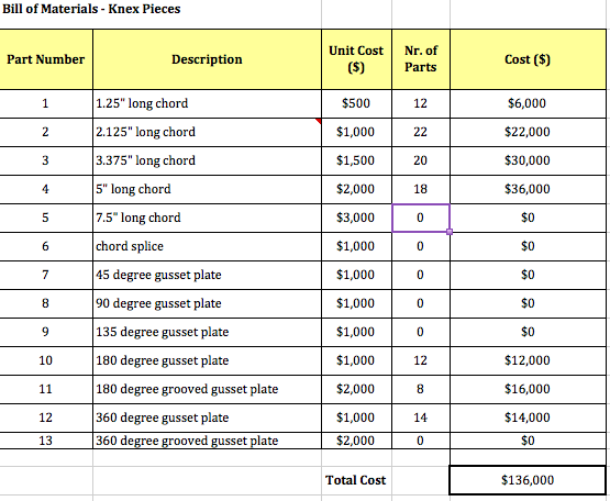
Figure 3: Truss Bill of Materials; the spreadsheet calculating the cost of the bridge.


Originally the bridge was designed with the sole goal of stability, this was then found to be way too expensive.  After this initial design a second design with the lowest possible cost was drawn up but after thinking through the execution of the design it was realized that it would be entirely too unstable.  Once the goal of a low cost to failure load ratio was considered more thoroughly many different designs that seemed to be a good compromise were drawn up.  Once the constraints came into consideration that above ground bridge seemed to be the most stable design and since the top of the bridge needed to have a flat top central region it was decided that keeping the entire top flat might be the most effective as it would help distribute the weight.
Designing this bridge taught me a lot about the difference between what works on the computer and what will actually work in the real world.  I also learned the importance of understanding all parameters and factors before creating a design as a design may be very strong or very pretty or very cheap but if it does not meet the constraints it useless.


WPBD vs. K'NEX - Durkin


K'NEX are a great hands on way to understand the structure of a bridge, in the same way that WPBD is a great way to learn about bridge structure.  Both use the basic ideas of joints and members in the construction of a bridge and both are great educational tools however past that there are very few similarities. A bridge built from K'NEX cannot bend in the same way that the bridges in WPBD can nor does a K'NEX bridge analyze the stress points in the way that WPBD does.  K'NEX also falls short in the types of members available as one cannot adjust the thickness of the members or the materials they are made from. One aspect of K'NEX that is not an option in WPBD is the ability to use different types of joint.  WPBD also does not allow for 3D changes in the way that K'NEX do. For example with K'NEX changes can be made to how the two sides of the bridge attach to each other, WPBD does not allow for this. Due to the lack of information K'NEX give about their weak points and how best to attach things a lot of this week will be spent testing different joints, attachment, and lengths of members in the hopes of building the most cost efficient bridge.

Sunday, April 22, 2012

Process Observations-Durkin


WPBD is an educational engineering program that can teach a student a lot about bridges but falls short in a number of areas when it comes to real world bridge design.  For example the program does not consider secondary members, three-dimensional stability of the bridge, or the many types of member failure. WPBD also does not consider how the bridge will hold up under environmental stresses or how it will effect its surrounding environment. This is important because the ground that the bridge is built on needs to be strong enough to support that bridge and the bridge need to be strong enough to with stand erosion that the ground and water will be under it. WPBD also does not take into consideration how the bridge would fair in the case of a natural disaster.  Leaving out these environmental factors makes it important to see WPBD as an educational program alone. The program also only takes things like cost and some measures of stability into consideration leaving out aesthetics and the amount that the bridge bends as criterion. WPBD also falls short when it comes to the type and distribution of weight that it considers when it comes to traffic. It only considers two types of traffic and traffic in only one direction when testing the bridge.  Also during testing the lateral position of the weight of traffic on the bridge is not considered. The program also does not use the exact cost of materials or consider the cost of labor to build the bridge as these can change with the economy and other factors.

~Jacquelyn Durkin

Wednesday, April 18, 2012

Research Question-Durkin

1) What is the longest bridge in the world?
2) What is the oldest bridge still standing today and what makes it so durable?
3) What is the most expensive bridge in the world?

~Jacquelyn Durkin

Tuesday, April 17, 2012

A1-Durkin


Dennis H. Mahan Memorial Bridge
Project ID: 00001A-
Designed By:
# Material Type Cross Section Size (mm) Length (m) Compression Force Compression Strength Compression Status Tension Force Tension Strength Tension Status
1 CS Solid Bar 140x140 3.61 0.00 2900.89 OK 684.28 4655.00 OK
2 CS Solid Bar 140x140 3.61 671.57 2900.89 OK 0.00 4655.00 OK
3 CS Solid Bar 140x140 3.61 0.00 2900.89 OK 467.64 4655.00 OK
4 CS Solid Bar 140x140 3.61 450.40 2900.89 OK 0.00 4655.00 OK
5 CS Solid Bar 140x140 3.61 0.00 2900.89 OK 393.02 4655.00 OK
6 CS Solid Bar 140x140 3.61 375.78 2900.89 OK 0.00 4655.00 OK
7 CS Solid Bar 140x140 3.61 0.00 2900.89 OK 304.45 4655.00 OK
8 CS Solid Bar 140x140 3.61 287.21 2900.89 OK 0.00 4655.00 OK
9 CS Solid Bar 140x140 3.61 0.00 2900.89 OK 199.87 4655.00 OK
10 CS Solid Bar 140x140 3.61 182.63 2900.89 OK 0.00 4655.00 OK
11 CS Solid Bar 140x140 3.61 49.70 2900.89 OK 95.17 4655.00 OK
12 CS Solid Bar 140x140 3.61 77.93 2900.89 OK 66.94 4655.00 OK
13 CS Solid Bar 140x140 3.61 154.43 2900.89 OK 0.00 4655.00 OK
14 CS Solid Bar 140x140 3.61 0.00 2900.89 OK 171.67 4655.00 OK
15 CS Solid Bar 140x140 3.61 258.94 2900.89 OK 0.00 4655.00 OK
16 CS Solid Bar 140x140 3.61 0.00 2900.89 OK 276.18 4655.00 OK
17 CS Solid Bar 140x140 3.61 346.97 2900.89 OK 0.00 4655.00 OK
18 CS Solid Bar 140x140 3.61 0.00 2900.89 OK 364.21 4655.00 OK
19 CS Solid Bar 140x140 3.61 422.18 2900.89 OK 0.00 4655.00 OK
20 CS Solid Bar 140x140 3.61 0.00 2900.89 OK 439.42 4655.00 OK
21 CS Solid Bar 140x140 3.61 650.53 2900.89 OK 0.00 4655.00 OK
22 CS Solid Bar 140x140 3.61 0.00 2900.89 OK 663.24 4655.00 OK
23 CS Solid Bar 140x140 4.00 0.00 2633.62 OK 752.09 4655.00 OK
24 CS Solid Bar 140x140 4.00 0.00 2633.62 OK 1231.45 4655.00 OK
25 CS Solid Bar 140x140 4.00 0.00 2633.62 OK 1611.73 4655.00 OK
26 CS Solid Bar 140x140 4.00 0.00 2633.62 OK 1877.15 4655.00 OK
27 CS Solid Bar 140x140 4.00 0.00 2633.62 OK 2008.20 4655.00 OK
28 CS Solid Bar 140x140 4.00 0.00 2633.62 OK 2004.55 4655.00 OK
29 CS Solid Bar 140x140 4.00 0.00 2633.62 OK 1866.21 4655.00 OK
30 CS Solid Bar 140x140 4.00 0.00 2633.62 OK 1593.46 4655.00 OK
31 CS Solid Bar 140x140 4.00 0.00 2633.62 OK 1206.67 4655.00 OK
32 CS Solid Bar 140x140 4.00 0.00 2633.62 OK 728.75 4655.00 OK
33 CS Solid Bar 140x140 5.39 491.54 1732.39 OK 0.00 4655.00 OK
34 CS Solid Bar 140x140 5.39 0.00 1732.39 OK 318.03 4655.00 OK
35 CS Solid Bar 140x140 5.39 598.41 1732.39 OK 0.00 4655.00 OK
36 CS Solid Bar 140x140 5.39 0.00 1732.39 OK 762.83 4655.00 OK
37 CS Solid Bar 140x140 5.39 499.18 1732.39 OK 0.00 4655.00 OK
38 CS Solid Bar 140x140 5.39 0.00 1732.39 OK 637.31 4655.00 OK
39 CS Solid Bar 140x140 5.39 387.70 1732.39 OK 0.00 4655.00 OK
40 CS Solid Bar 140x140 5.39 0.00 1732.39 OK 486.29 4655.00 OK
41 CS Solid Bar 140x140 5.39 251.32 1732.39 OK 0.00 4655.00 OK
42 CS Solid Bar 140x140 5.39 0.00 1732.39 OK 330.06 4655.00 OK
43 CS Solid Bar 140x140 5.39 95.18 1732.39 OK 132.78 4655.00 OK
44 CS Solid Bar 140x140 5.39 89.73 1732.39 OK 173.72 4655.00 OK
45 CS Solid Bar 140x140 5.39 0.00 1732.39 OK 289.06 4655.00 OK
46 CS Solid Bar 140x140 5.39 245.94 1732.39 OK 17.60 4655.00 OK
47 CS Solid Bar 140x140 5.39 0.00 1732.39 OK 445.34 4655.00 OK
48 CS Solid Bar 140x140 5.39 383.00 1732.39 OK 0.00 4655.00 OK
49 CS Solid Bar 140x140 5.39 0.00 1732.39 OK 596.50 4655.00 OK
50 CS Solid Bar 140x140 5.39 496.79 1732.39 OK 0.00 4655.00 OK
51 CS Solid Bar 140x140 5.39 0.00 1732.39 OK 723.23 4655.00 OK
52 CS Solid Bar 140x140 5.39 600.45 1732.39 OK 0.00 4655.00 OK
53 CS Solid Bar 140x140 5.39 0.00 1732.39 OK 305.21 4655.00 OK
54 CS Solid Bar 140x140 5.39 478.87 1732.39 OK 0.00 4655.00 OK
55 CS Solid Bar 140x140 4.00 234.50 2633.62 OK 0.00 4655.00 OK
56 CS Solid Bar 140x140 4.00 421.01 2633.62 OK 0.00 4655.00 OK
57 CS Solid Bar 140x140 4.00 419.34 2633.62 OK 0.00 4655.00 OK
58 CS Solid Bar 140x140 4.00 457.78 2633.62 OK 0.00 4655.00 OK
59 CS Solid Bar 140x140 4.00 487.46 2633.62 OK 0.00 4655.00 OK
60 CS Solid Bar 140x140 4.00 488.39 2633.62 OK 0.00 4655.00 OK
61 CS Solid Bar 140x140 4.00 460.53 2633.62 OK 0.00 4655.00 OK
62 CS Solid Bar 140x140 4.00 423.59 2633.62 OK 0.00 4655.00 OK
63 CS Solid Bar 140x140 4.00 425.90 2633.62 OK 0.00 4655.00 OK
64 CS Solid Bar 140x140 4.00 242.37 2633.62 OK 0.00 4655.00 OK
65 CS Solid Bar 140x140 3.61 210.26 2900.89 OK 0.00 4655.00 OK
66 CS Solid Bar 140x140 3.61 0.00 2900.89 OK 429.42 4655.00 OK
67 CS Solid Bar 140x140 3.61 451.36 2900.89 OK 0.00 4655.00 OK
68 CS Solid Bar 140x140 3.61 0.00 2900.89 OK 434.12 4655.00 OK
69 CS Solid Bar 140x140 3.61 302.36 2900.89 OK 0.00 4655.00 OK
70 CS Solid Bar 140x140 3.61 0.00 2900.89 OK 285.12 4655.00 OK
71 CS Solid Bar 140x140 3.61 197.14 2900.89 OK 0.00 4655.00 OK
72 CS Solid Bar 140x140 3.61 0.00 2900.89 OK 179.90 4655.00 OK
73 CS Solid Bar 140x140 3.61 114.10 2900.89 OK 13.61 4655.00 OK
74 CS Solid Bar 140x140 3.61 30.85 2900.89 OK 96.86 4655.00 OK
75 CS Solid Bar 140x140 3.61 31.27 2900.89 OK 96.34 4655.00 OK
76 CS Solid Bar 140x140 3.61 113.57 2900.89 OK 14.03 4655.00 OK
77 CS Solid Bar 140x140 3.61 0.00 2900.89 OK 179.27 4655.00 OK
78 CS Solid Bar 140x140 3.61 196.51 2900.89 OK 0.00 4655.00 OK
79 CS Solid Bar 140x140 3.61 0.00 2900.89 OK 283.79 4655.00 OK
80 CS Solid Bar 140x140 3.61 301.03 2900.89 OK 0.00 4655.00 OK
81 CS Solid Bar 140x140 3.61 0.00 2900.89 OK 430.79 4655.00 OK
82 CS Solid Bar 140x140 3.61 448.03 2900.89 OK 0.00 4655.00 OK
83 CS Solid Bar 140x140 3.61 0.00 2900.89 OK 422.27 4655.00 OK
84 CS Solid Bar 140x140 3.61 209.00 2900.89 OK 0.00 4655.00 OK
85 CS Solid Bar 140x140 4.00 611.63 2633.62 OK 0.00 4655.00 OK
86 CS Solid Bar 140x140 4.00 1077.31 2633.62 OK 0.00 4655.00 OK
87 CS Solid Bar 140x140 4.00 1362.86 2633.62 OK 0.00 4655.00 OK
88 CS Solid Bar 140x140 4.00 1517.60 2633.62 OK 0.00 4655.00 OK
89 CS Solid Bar 140x140 4.00 1566.25 2633.62 OK 0.00 4655.00 OK
90 CS Solid Bar 140x140 4.00 1509.14 2633.62 OK 0.00 4655.00 OK
91 CS Solid Bar 140x140 4.00 1357.12 2633.62 OK 0.00 4655.00 OK
92 CS Solid Bar 140x140 4.00 1077.42 2633.62 OK 0.00 4655.00 OK
93 CS Solid Bar 140x140 4.00 618.34 2633.62 OK 0.00 4655.00 OK
94 CS Solid Bar 140x140 7.81 256.46 820.46 OK 0.00 4655.00 OK
95 CS Solid Bar 140x140 7.81 255.64 820.46 OK 0.00 4655.00 OK
96 CS Solid Bar 140x140 2.00 41.62 3876.74 OK 0.00 4655.00 OK
97 CS Solid Bar 140x140 5.00 587.08 1970.68 OK 0.00 4655.00 OK
98 CS Solid Bar 140x140 2.00 40.38 3876.74 OK 0.00 4655.00 OK
99 CS Solid Bar 140x140 5.00 592.88 1970.68 OK 0.00 4655.00 OK
100 CS Solid Bar 140x140 6.40 0.00 1220.68 OK 477.56 4655.00 OK
101 CS Solid Bar 140x140 6.40 0.00 1220.68 OK 481.60 4655.00 OK
102 CS Solid Bar 140x140 5.00 329.39 1970.68 OK 0.00 4655.00 OK
103 CS Solid Bar 140x140 5.00 332.44 1970.68 OK 0.00 4655.00 OK


 My goal for the design of this bridge was to design a bridge that is both stable and inexpensive.  I went through multiple trials before deciding on this design.  Originally I tried adding X’s instead of triangles however that seemed to add little to no stability while greatly increasing the cost. I began with a simple single level, above the road bridge design but found this to be very unstable throughout the structure. I then added extra cross beams at the ends of the bridge; this made the bridge better connected to the ground.   This fixed the initial brake that occurred during the test but still left the center of the bridge very weak.  After adding an upper layer to the single level design the bridge became more stable but was still very strained toward the center.  I then added support below which made the bridge better able to support the truck as it drove across.  Adding the layer below also seemed to help distribute the weight of the truck more evenly as there was no longer one or two points on the bridge that were under great strain at any time. Also keeping the beams of the lower layer short helped keep costs low.  I chose to stick with the original beams as opposed to switching to tubes as each time a test was done with tubes instead of beams the bridge lost stability.  This loss of stability occurred regardless of where the tube replaced the beam showing that the weight is evenly distributed.  The cut in cost that using the tubes would achieve was not worth the lack of stability they would cause. Overall the cost of the bridge came to $605,811.49.
            By using the Westpoint Bridge Designer program I learned more about stability as well as how to use features such as how to use the Compression Force/Strength Analysis to better determine which areas need more support.  I also learned about the general structure necessary to make a strong and cost efficient bridge. I found that straight lines are incredibly unstable and that although very stable X’s are not very cost efficient. I learned that symmetry was a key characteristic to a strong structure, as one side being weaker than the other would nearly always lead to a brake in the bridge. It was important to be patient during this process and to be constantly testing as each added or taken away beam could make a significant difference.
     In the week to come our group will discuss the different features of our final designs.  We will than compare and contrast the bridges to see what needs to be modified and what should be included in our final group design.  We will try and find the most cost efficient and stable properties of each bridge.

~Jacquelyn Durkin